Motivation
As you may have seen in earlier articles, I produce my own PCBs at home with the toner transfer method. After some experimentation the PCB quality is quite satisfactory, but drilling the holes for even a moderate number of through-hole components is very tiresome.
When you design your PCBs with a proper CAD software (such as KICAD), you have the coordinates of all drill holes anyway, so how about making an automated moving drill press table which moves the PCB to the places where holes are desired? But calibrating the coordinate system on the PCB should be quick and reliable.

Acquiring a coordinate table and motorizing it

So I got a “Proxxon MICRO compound table KT 70”. The table has two axes with two cranks. At the rear end each axis has a cap that, once removed, reveals a 10 mm hexagon nut. This nut is very tightly attached to the spindle, so it can be used to exert force and move the table.

From pollin.de (surplus store) I got two cheap bipolar stepper motors that I attached to the spindles using 10mm ratchet wrench sockets. I used a Dremel to cut a slit in the stepper motor shaft and inserted a small piece of metal sheet. The other side of the sheet has the exact dimensions to fit diagonally into the square hole of the wrench socket.


Everything is kept in place with metal angles, screws and small blocks of wood.
Motor drivers

I built some motor drivers from discrete components (I didn’t know the good old L298 back then). Each motor has two coils. Each coil is operated with an H-bridge (or full bridge) circuit as shown above. It allows you to pass current in either direction through the coil or turn the coil off completely. There are no protection diodes, because the datasheets of the selected FETs claim that they are already included in the package. I built the driver circuit on a perfboard, because … why not.


Microcontroller + USB + tactile interface
Onto the motor driver board I soldered an ATMega32u2 microcontroller breakout board which I had previously designed and etched. The ATMega32u2 has a native USB interface which can be used to communicate with the microcontroller at runtime, but also to flash the firmware without the need of an extra programmer.


Pollin.de was selling old touchpads (“TM1001a”) for 35 cents until recently. It needs a supply voltage of 5V and has only one bi-directional data line which is connected to a simple GPIO pin of the microcontroller. I found a code snippet on microcontroller.net and built an AVR lib around it, which makes it easy to get information about either relative or absolute movements.
In this application the movement of the compound table follows the swiping of a finger on the touchpad. As soon as the table has reached the target position, the current through the motor coils is switched off.
Above the touchpad I put a little console with three switches + LEDs. The left and the middle switch enable/disable swipe movement in x and/or y direction. The right switch controls a relay that cuts the power to a dedicated drilling machine power outlet.
I used the LUFA AVR library for implementing a USB COM port on the ATMega32u2. Connected to a Linux machine, it shows up as “/dev/ttyACM0” and can be accessed like a normal serial device (no driver installation needed). It should work on Windows, too, therefore LUFA provides “LUFA USBtoSerial.inf” as driver information.
The interface between the microcontroller and the PC is fairly simple:
Upon receiving a line break or return character, the current table position in x and y are printed back:
x_pos: - 0.250 y_pos: + 26.083
Of course these readings are updated, when the table is moved by means of the touchpad.
The table understands the commands like the following:
gx10.5
gy-4
which means go to coordinates x = 10.5 mm and y = -4 mm
Relative movements are also possible:
mx10
my-1.234
If you just type “z”, the internal x and the y coordinates of the table are set to zero at the current position.
All commands have to be confirmed with a return or a line break.
PC software + calibration procedure
On the PC side of the USB cable I want to have a software that “eats” drl files (containing drill coordinates) and makes the compound table move the PCB underneath the drill to all the right places.
In KICAD you find the export tool for drl files under “File/Plot” -> “Generate Drill File”. It would be nice if you could select millimeters as length units and decimal format. All other CAD softwares … no clue.
Extracting the coordinates of the drl file and generating a series of move commands for the compound table was a nice Perl scripting exercise, but quite straightforward. The tricky/fun part is the calibration of the coordinate system. By that I mean the alignment of the coordinates of the holes from the drl file and the places in the physical PCB where the holes need to be drilled.
When I cut out a self-etched PCB, the edges are not perfectly straight and the margins vary, so aligning the PCB by pushing it against some kind of ruler or stop is not going to work. So I fix the PCB on the compound table and have to accept that the hole coordinates on the PCB (in the drill press frame of reference) differ from the CAD coordinates in terms of a random shift and a random rotation. But knowing the coordinates of two distinct points in each frame of reference should allow me to calculate all parameters of a coordinate transformation function which can then be used to transform all CAD coordinates to (shift + rotation corrected) drill press coordinates.
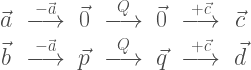
As points of reference I used the most top left and the most bottom right drill hole on the respective PCB. The Perl script automatically finds these coordinate pairs in the drill file and stores them as vectors 


The question is now: How do we get from

First we shift all coordinates by subtracting 


Okay, we already have

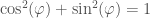
But since we’re not interested in the actual angle, we can simplify it and say

by defining

These two are the unknowns we need to find!
(don’t confuse 

We stated that
ergo


now we can reorganize the elements on the left side without changing the result of the matrix-vector multiplication:

We summarize all the 


We can solve for 

Fortunately for us, inverting a 2×2 matrix (like for example 

therefore:
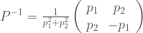
and finally

So with the following function 

using:

cool eh?!
Now there’s just one more little thing. What if, due to measurement errors, 


Conclusion
I like my machine, it really works great (usually tools that I build break after a while or they turn out too complicated to use in everyday situations). The perl script is ugly as hell but it does the job. Maybe one day I will make a front-end that shows me a picture of all drill holes and a cross that moves, according to the position of the drill. That would be fancy. I hope I didn’t bore you to death with the math.
Downloads

Nice work 🙂 Now if you just motorise the z axis (the pillar), you’d have a full on CNC mill… Interesting to see your use of a touchpad – good to know they can have a bit more life. Cheers!
Pingback: Semi-Auto PCB Drill Press Makes Drilling Semi-Painless | Hackaday·
Pingback: Semi-Auto PCB Drill Press Makes Drilling Semi-Painless | 0-HACK·
Pingback: Semi-Auto PCB Drill Press Makes Drilling Semi-Painless | Ad Pub·
Pingback: Semi-Auto PCB Drill Press Makes Drilling Semi-Painless | Hack The Planet·
what drill did you use? Proxxon? Also, its not motorized or is?
The drilling machine is a quite oversized Bosch (with hammer drill). It’s fixed to a drill rig from the hardware store, which is manually operated with a lever.
Hi would like to know if the perl program can run in windows 7 64 bit thanks and regards shailesh
Hi! I’ve never tried it on Windows. But it should be (quite) platform independent. You need to have a Perl interpreter installed on Windows, like for example strawberry perl (http://strawberryperl.com/). And you need to install somehow the “Device::SerialPort” perl module. I don’t know if it’s included in the strawberry perl distribution. But it’s on CPAN.
Let me know how you manage!
best wishes
Micha
Else its a nice project u have
Pingback: Automated PCB Drill Press - Hacked Gadgets – DIY Tech Blog·
Pingback: Automated PCB Drill Press • W1GNL WebsiteW1GNL Website·
Wonderfull, thanks for the great explanation, especially about the involved math!
Danke dir !
Do you have some technical data on the stepper motors? (e.g. step size, current draw, rotational force)? The KT70 compound table needs some serious force to be moved…
I really like the idea of mounting them using the hex nut, this is much simpler than going via the spindle.
Hi. I don’t have much information about the motors. They are bipolar stepper motors with 24 steps per revolution. The maximum current is rated at 300mA per coil. To move the table, however, I need to run them at 600mA. That’s why I supply the motor driver with 18V DC. I turn off the current when the table is not moving and I don’t operate it for hours in a row. So far the motors live and everyone is happy.
This is a lovely project, and is nicely executed. I guess time has moved on since you did all this development. Nowadays, you could use pre-built drivers and simply run LinuxCNC (although not on that chip). It has G codes which can cope with the initial orientation (using much the same maths, I would guess).
Your little touch pad interface is nice, and I have not seen that used before, instead of a button or MPG detent-style pendant.
I guess you learned a lot during development, which is really the whole point of doing something like this.
Bravo!
Yup, a lot of cool stuff is around these days 🙂 And my need for reinventing the wheel all the time greatly diminished 😛 Thanks for the flowers!